![DINA_Logo_RGB-3.png]](https://knowledge.dina.de/hs-fs/hubfs/DINA_Logo_RGB-3.png?width=200&height=90&name=DINA_Logo_RGB-3.png)
The following pin assignment applies to the BIV connector shown in the ‘Encoder Adapter BiSS’ connection diagram:
| Signal | Funktion | RJ45-Kabel BIV |
| MA+ | BiSS-C clock line, output | 7 |
| SLO+ | BiSS-C data line, input | 3 |
| 5V |
5V sensor power supply |
2 |
| MA- |
BiSS-C clock line, inverted output |
8 |
| SLO- |
BiSS-C data line, inverted input |
6 |
| GND | Potential for sensor power supply | 1 |
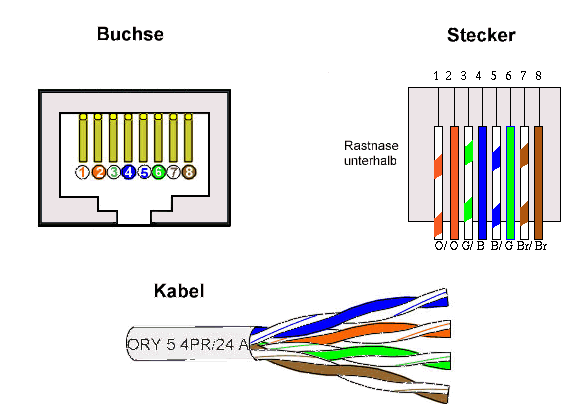
How do you read the pin numbering?
The connection diagram shows the RJ45 socket from the front, with the recess for the locking tab at the bottom. In this view, the pins are numbered from left to right as 1 to 8. When wiring, refer to the diagram shown to avoid a mirror-reversed pin assignment.