START A NEW DIAGNOSIS
With the button ![]() the user can start the rack diagnosis.
the user can start the rack diagnosis.
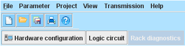
The program requires a short time to read out all needed information from the main module.
Please do not do an action while “Please wait” appears.
It starts with the standard diagnosis, in accordance with button 1.
All modules in the rack are selected for the diagnosis loop.
All status information from the modules will be read out an displayed. By highlighting the module in red errors are shown immediately.
Error evaluationintherackdiagnosis
There are two kinds of errors:
- SLOK-Off errors: Incorrect operating status of the SafeLine system (e.g. internal errors)
- Plausibility errors: incorrect operating status of external connectors (e.g. 2 input for OMS are logic high)
If an error is detected on a module, the rectangle where the slot number is shown is highlighted in red.
A click on this rectangle opens a window where the errors are described in more detail.
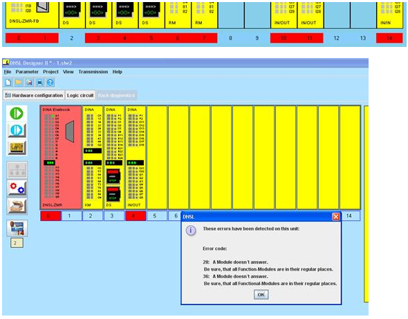
SLOK-Off errors have an error code between 1 till 18 and 24 till 64.
Errors with error code above 64 are not SLOK-Off errors. They point out that somewhere is an incorrect but not critical state. For example: More than one input of the OMS is at logic high level.
ERROR - DIAGNOSIS

SLOK-Off errors will be considered separately like in the Designer versions before with a click on the button:
After a click on the button, the following window appears.
All possible failures shown here, except errors 19 till 23, are SLOK-Off errors.
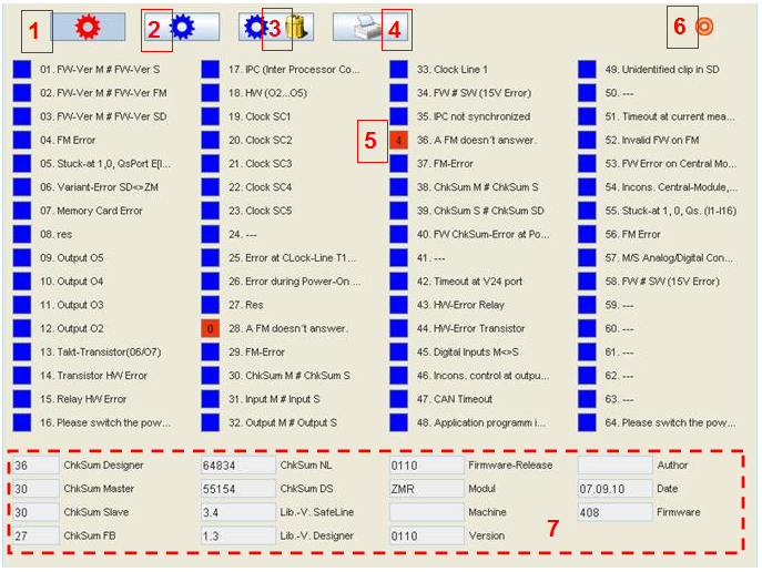
- Red diagnosis button: Current errors are displayed.
If this button is activated current errors will be read out from the main module and displayed. - Blue diagnosis button: Saved errors can be read out from the main module where they saved in the internal EEPROM.
All errors will be saved in the internal EEPROM so they can be represented after a power failure. - Button 3: Delete saved errors on the main module. If the main module is configured with a password, you will need it to delete the errors.
- Button 4: Print the errors
The actual error mask (actual errors or saved errors) can be print out into a pdf-document for documentation. - If a corresponding error was detected, the rectangle is red with the accordingly slot number inside it. With a click on this rectangle, detailed information about the error appears in a new window.
- ComPort status:
The colour of the circle changes from red to green if a connection to the main module is established. - In this area are a lot of information about the application, main module like firmware, checksum and user-specific (author and machine) details are displayed.